
The J30J series micro-rectangular electrical connectors feature the following performance attributes:
- Compact size and lightweight design: Characterized by miniaturization and lightweight construction, the product can be deployed in confined spaces, catering to applications with stringent requirements for space occupancy and equipment weight reduction.
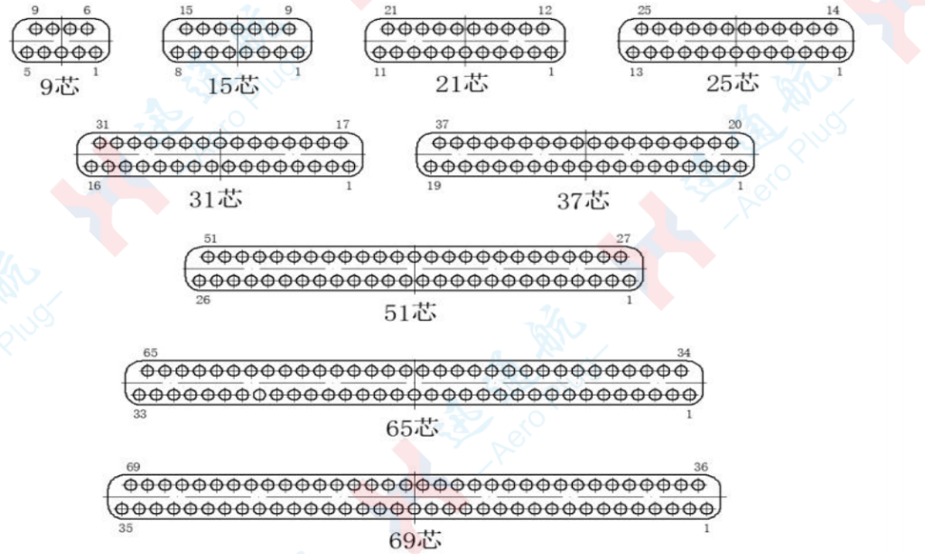
- High connection density: With a contact pitch of 1.27mm, the connector offers a diverse range of pin configurations from 9 to 144 pins. It enables high-density wiring, facilitating the transmission of a large volume of signals and power within a limited spatial envelope.
- Excellent mechanical performance: Boasting superior resistance to vibration and shock, the connector can withstand sustained vibration with a frequency range of 10–2000Hz and acceleration of 294m/s², as well as shock impact with acceleration of 980m/s² and duration of 6ms. It achieves a mechanical mating durability of up to 1000 cycles, ensuring reliable long-term operation.
- Superior electrical performance: The connector exhibits a rated withstand voltage of 800V under ambient temperature conditions. Its insulation resistance measures ≥5000MΩ at room temperature and ≥100MΩ in humid-heat environments, effectively preventing electrical breakdown and leakage. Operating across a wide temperature range of -55℃ to 125℃, it is adaptable to diverse ambient temperature conditions.
- Optimal shielding performance: Equipped with a metal shielding housing, the connector delivers excellent electromagnetic shielding capability, which can effectively suppress electromagnetic interference (EMI) and ensure stable signal transmission.
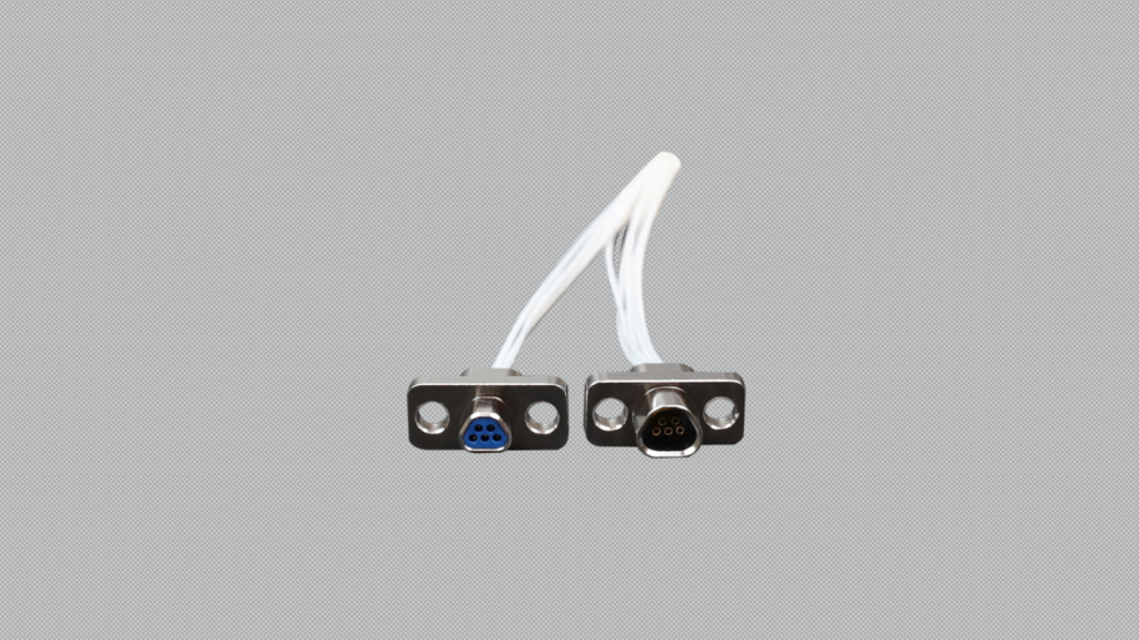
- Reliable connection mechanism: Adopting a threaded locking structure between plug and socket, the connector incorporates guiding and anti-misinsertion functions. These features guarantee precise and secure mating, preventing accidental disconnection.
The J30J series micro-rectangular electrical connectors are primarily composed of housing, insulator, contacts, locking assembly and rear accessories. A detailed structural breakdown is provided below:
- Core Components
- Housing: Typically fabricated from metallic materials such as aluminum alloy, it combines robust structural strength with effective shielding performance. It can effectively isolate external electromagnetic interference and protect internal contacts and insulators from environmental hazards and mechanical damage.
- Insulator: Generally made of insulating materials like engineering plastics, it serves to position and isolate individual contacts. It ensures electrical insulation between contacts and between contacts and the housing, thereby preventing short-circuit faults.
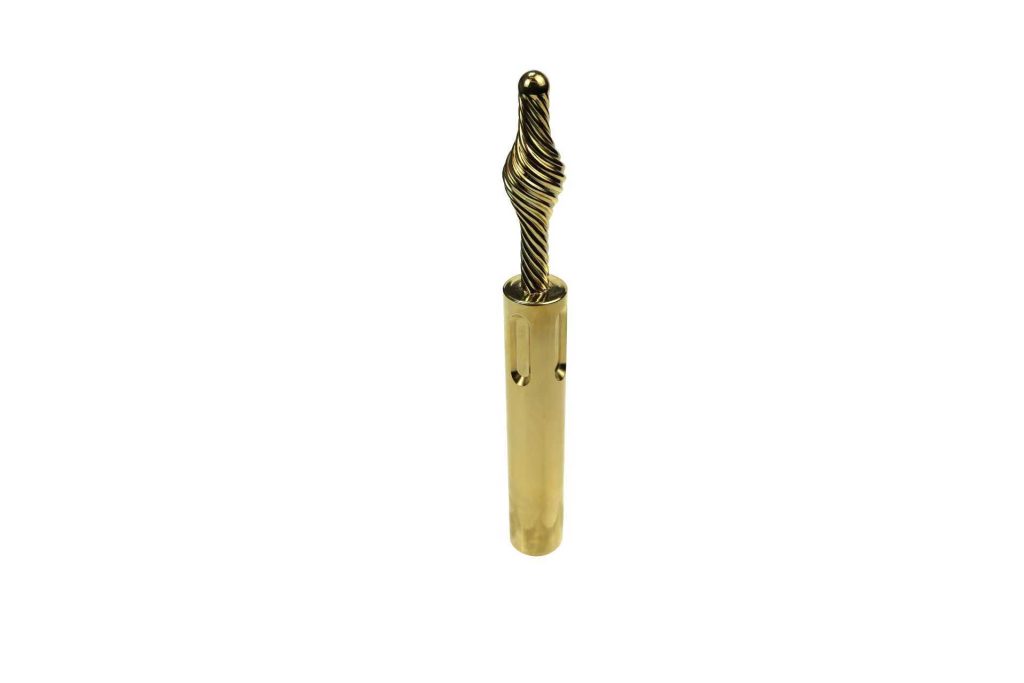
- Contacts: As the core functional components enabling electrical connection, the plug side utilizes stranded elastic contacts (commonly referred to as twist pins), each featuring seven contact points, while the socket side is configured with receptacles. This design enhances contact reliability and ensures stable transmission of signals and current.
- Auxiliary Components
- Locking assembly: Consisting of screws, sleeves, mounting brackets, flat washers, spring washers and nuts, the assembly is categorized into free-end locking components and fixed-end locking components. It is primarily used for threaded locking between plug and socket, as well as for rigid mounting of the electrical connector on chassis panels or printed circuit boards (PCBs).
- Rear accessories: Including backshells, cable clamps, cable clips and grounding tabs, these accessories are designed to protect the contact tails and wires at the rear of the connector from damage, secure the cable routing, and provide auxiliary electromagnetic shielding and reliable grounding.
The fundamental operating principle of the micro-rectangular electrical connector relies on the precise mating of corresponding contacts between plug and socket to achieve electrical connection, while leveraging mechanical structures to ensure connection stability and reliability. This principle can be elaborated on two core levels as follows:
- Electrical Connection Principle
- The core mechanism involves the physical contact between contacts (elastic pins on the plug side and receptacles on the socket side) to enable current or signal transmission.
- When inserted into the receptacle, the elastic-structured pins (e.g., the commonly used stranded twist pins) undergo elastic deformation, closely fitting the inner wall of the receptacle to form a stable conductive path, which ensures low contact resistance and excellent electrical conductivity.
- The insulator precisely positions each contact pair and isolates individual conductive paths through its material insulation properties, preventing signal crosstalk and short circuits.
- Mechanical Fixation Principle
- The locking structure (such as threads or buckles) tightly engages the plug and socket, preventing disconnection caused by external mechanical stresses such as vibration and shock.
- Certain models are integrated with guiding and anti-misinsertion structures (e.g., locating pins and specific keyways), which restrict the plug and socket to mate only in the correct orientation, avoiding component damage or poor contact due to incorrect insertion.
- The metal housing not only provides mechanical protection for internal components but also acts as an electromagnetic shield to reduce external interference, while enhancing the overall structural rigidity of the connector.
In simple terms, the J30J series micro-rectangular electrical connectors realize stable transmission of signals and current through precise mechanical mating to ensure reliable contact of conductive components. It is ideally suited for applications with constrained space and high reliability requirements.
1. Typical Application Scenarios and Industry Compatibility
Leveraging the aforementioned structural and performance advantages, the J30J series micro-rectangular electrical connectors are widely compatible with industries that impose stringent requirements on space constraints, connection reliability and electromagnetic compatibility (EMC), as detailed below:
- Military and aerospace sector: The connector can be integrated into radar systems, UAV flight control modules, missile-borne electronic equipment, satellite communication terminals and other aerospace platforms. This sector demands equipment to operate under extreme conditions such as high-altitude low temperature, intense vibration and strong electromagnetic radiation. The connector’s wide operating temperature range, vibration and shock resistance, and electromagnetic shielding performance ensure long-term stable service of the equipment.
- Industrial automation control sector: It is suitable for PLC control cabinets, servo drives, motion control cards, industrial robot joint modules and other equipment. With a contact pitch of 1.27mm and multiple pin configurations, it enables integrated transmission of control signals and drive power. The threaded locking structure can effectively resist mechanical vibration interference in industrial field environments, avoiding production line failures caused by signal interruption.
- Communication equipment sector: The connector is applicable to base station signal processing units, RF modules, portable communication terminals and other products. Its high connection density meets the miniaturization and integration design requirements of communication equipment, and its excellent electrical insulation performance ensures the integrity of high-frequency signal transmission, preventing signal crosstalk.
- High-end instrumentation sector: It is ideal for precision test and measurement equipment, medical electronic instruments, embedded development boards and other devices. The miniaturized structure can adapt to the compact wiring space inside the instruments, and the stable contact resistance and mating durability can ensure the accuracy of test data and the long-term operational reliability of the equipment.

2. Industry Standard Compliance and Reliability Verification
- Industry standard complianceThe design, manufacturing and testing of the J30J series products fully comply with a number of national and industry standards, with core compliance including:
- GJB 2889-1997 General Specification for Micro-Rectangular Electrical Connectors, meeting the reliability and environmental adaptability requirements of military equipment for connectors;
- SJ 20508-1995 General Specification for Micro-Rectangular Electrical Connectors, standardizing the dimensional tolerances, electrical performance and test methods of the products;
- IEC 60512 Connectors for Electronic Equipment – Tests and Measurements, ensuring the compatibility of products with the international market.
- Reliability verification testsPrior to delivery, all products undergo rigorous multi-dimensional testing to verify their performance stability under extreme operating conditions. Key test items and technical indicators are as follows:
- Environmental adaptability test: Passing high and low temperature cycle tests (≥10 cycles) ranging from -55℃ to 125℃, and steady-state damp heat tests (≥96h) at 40℃ with relative humidity of 95%, with no degradation in insulation resistance and withstand voltage performance after testing;
- Mechanical durability test: After 1000 mating cycles, the contact resistance variation is ≤20mΩ, meeting the requirements for long-term use;
- Electromagnetic compatibility (EMC) test: Achieving an electromagnetic shielding effectiveness of ≥40dB within the frequency range of 10kHz to 1GHz, effectively suppressing external electromagnetic interference;
- Mechanical performance test: Withstanding random vibration tests with frequency range of 10-2000Hz and shock tests with acceleration of 980m/s², with no structural damage or contact detachment after testing.
3. Key Guidelines for Selection and Application
- Pin configuration selection principle: Select the appropriate pin count based on the quantity and type of signals and power to be transmitted. For signal transmission, 9–51 pin configurations are preferred; for hybrid transmission of signals and power, high-density 64–144 pin configurations are available. This avoids space waste caused by redundant pin counts.
- Mounting method selection: For chassis panel mounting applications, fixed-end locking assemblies are preferred; for printed circuit board (PCB) mounting applications, wire-to-board or surface-mount structures can be selected to ensure mechanical stability after installation.
- Environmental protection requirements: In harsh environments with high humidity and salt spray, it is recommended to select connectors with nickel-plated or gold-plated contacts and housings to enhance corrosion resistance. In environments with strong electromagnetic interference, ensure reliable grounding of the grounding tabs in the rear accessories to strengthen the electromagnetic shielding effect.
- Mating and unmating operation specifications: Apply force smoothly along the direction of the guide key during mating and unmating to avoid bending deformation of contacts caused by tilted insertion or extraction. Tighten the locking threads with appropriate torque to prevent thread slipping or housing damage due to over-tightening.
Terminology Specification Notes
- Key technical terms are translated in accordance with international standards for electrical connectors, e.g., anti-misinsertion function (not “error-proof insertion”), mating durability (not “plugging service life”).
- All performance parameters retain their original numerical values and units, with unit symbols formatted to comply with SI standards (e.g., m/s² instead of m/s^2, MΩ instead of M ohm).
- National military standards and industry standards retain their original codes and are supplemented with English standard names to facilitate international technical communication.
.png)
-1.png)